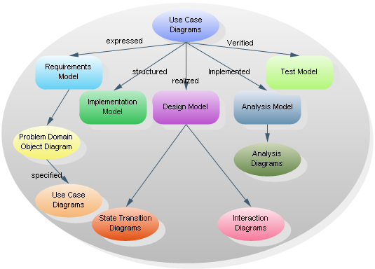
Fast Forward to Use Case Diagrams
 |
|
Use the space bar or right arrow for next slide,
left arrow to back up. Use 'a' key to toggle between single
page and slide modes.
 |
|
Use the space bar or right arrow for next slide,
left arrow to back up. Use 'a' key to toggle between single
page and slide modes.
The establishment and use of sound engineering principles in order to obtain economically software that is reliable and works efficiently on real machines. [Classic Definition 1969]
(1) The application of a systematic, disciplined, quantifiable approach to the development, operation, and maintenance of software; that is the application of engineering to software. (2) The study of approaches as in (1). [IEEE 1993]
The application of a systematic, disciplined, quantifiable approach to the development, operation, and maintenance of software. [Wikipedia 2010]

|

|
Diagram reproduced from http://en.wikipedia.org/Waterfall_model.
|

|
|

|

Swing cartoon from www.dons.net.au. One of several variations on this theme that are widely reproduced. Original artist unknown.
Object-Oriented Analysis and Design frames the definitions and models in terms of objects
A modeling language provides notations for describing abstract views of software applications domains and software systems, at various levels of abstraction.
Similar-looking modeling techniques may be applied in both phases, but the goals are different -- to modeling the problem versus modeling the solution.
Use cases are not exclusively a feature of object oriented analysis and design; they are applicable to non-OO methods as well as OO. However, they plan an important role in all phases of the UP, starting with requirements analysis.
Key question: "How can using the system provide observable value to the user, or fulfill their goals"?
Answers 3 questions:
|
As a <type of user>, I want <some behavior from the system> so that <some value is achieved> |

Larman says only novices and academics are preoccupied with diagrams and relationships, but they are fun and can be very helpful for visually oriented people.

A standard form of use case diagram is defined in the Unified Modeling Language.
Diagram reproduced from http://www.cc.gatech.edu/classes/AY2004/cs2335_summer/umlex/UseCaseDiagram1.jpg.
|

|
The UML and the UP (Unified Process) both contain the word "unified" but are distinct. The UP happens to make use of UML, the UP comprises many other elements. Moreover, UML and the UP have distinct histories.


In various UML diagrams, including use case diagrams, there are several kinds of lines used to show relationships. These are the ones that can be included in use case diagrams.
It seems, from examples published on the Web, that there is some variation in the conventions for usage of these lines and annotations. The conventions shown here come from the Rational/IBM documentation.


This applies also to use case descriptions.
Diagram reproduced from www.edrawsoft.com.